TLS background
Displacement of groups of atoms can be modeled by the TLS formalism presented in detail by Schomaker and Trueblood (1968). The TLS formalism describes a rigid-body displacement with three tensors T, L, and S for Translation, Libration, Screw. Useful qualitative and quantitative explanations of the TLS formalism summaries are presented by Winn, Isupov and Murshudov (2001), Painter and Merritt (2005, 2006). All of the papers above are references for this page.
T and L are symmetric 3x3 tensors with units in Å2 and radians2, respectively. The translation tensor T describes the anisotropic translational displacement for the atoms in the rigid body and is analogous to the individual anisotropic mean-square displacement tensor U. The rotation of the rigid body is described by the libration tensor L. The screw tensor S describes the correlation between the rotation and translation of a rigid body undergoing rotation about three non-intersecting orthogonal axes.
Here, we consider the total ADP to have 3 contributions: U = Ucrystal + UTLS + Uatom,residual
The overall anisotropy Ucrystal is generally modeled using a single anisotropic scale factor. The isotropic component of the overall scale factor is usually included in the B-factors, but in some PDB files this is not the case. UTLS can be related to the T, L, and S tensors, their origin, and an atom in the TLS group located at x, y, z as:
UTLS11 = L22z2+ L33y2- 2L23yz+ 2S21z- 2S31y+ T11
UTLS22 = L11z2+ L33x2- 2L31xz- 2S12z+ 2S32x+ T22
UTLS33 = L11y2+ L22x2- 2L12xy- 2S23x+ 2S13y+ T33
UTLS12 = -L33xy+ L23yxz- L13yz- L12z2- S11z+ S22z+ S31x- S32y+ T12
UTLS13 = -L22xz+ L23yx- L13y2+ L12yz+ S11y- S33y+ S23z- S21x+ T13
UTLS23 = -L11yz- L23x2+ L13xy+ L12xz- S22x+ S33x+ S12y- S13z+ T23
A TLS model can be interpreted as a sum of 6 independent displacements: 3 screw librations about non-intersecting axes and 3 translations. The program TLSView (Painter and Merrit, 2005) is very useful for visualizing the TLS motion.
Modeling Uatom,residual is described here. The B-factor in PDB files is usually the sum of the isotropic components of Ucrystal, UTLS, and Uatom,residual.
Additional analyses: PDB versus BDB
Several analyses of the (differences between) PDB and BDB files are described in the BDB paper.
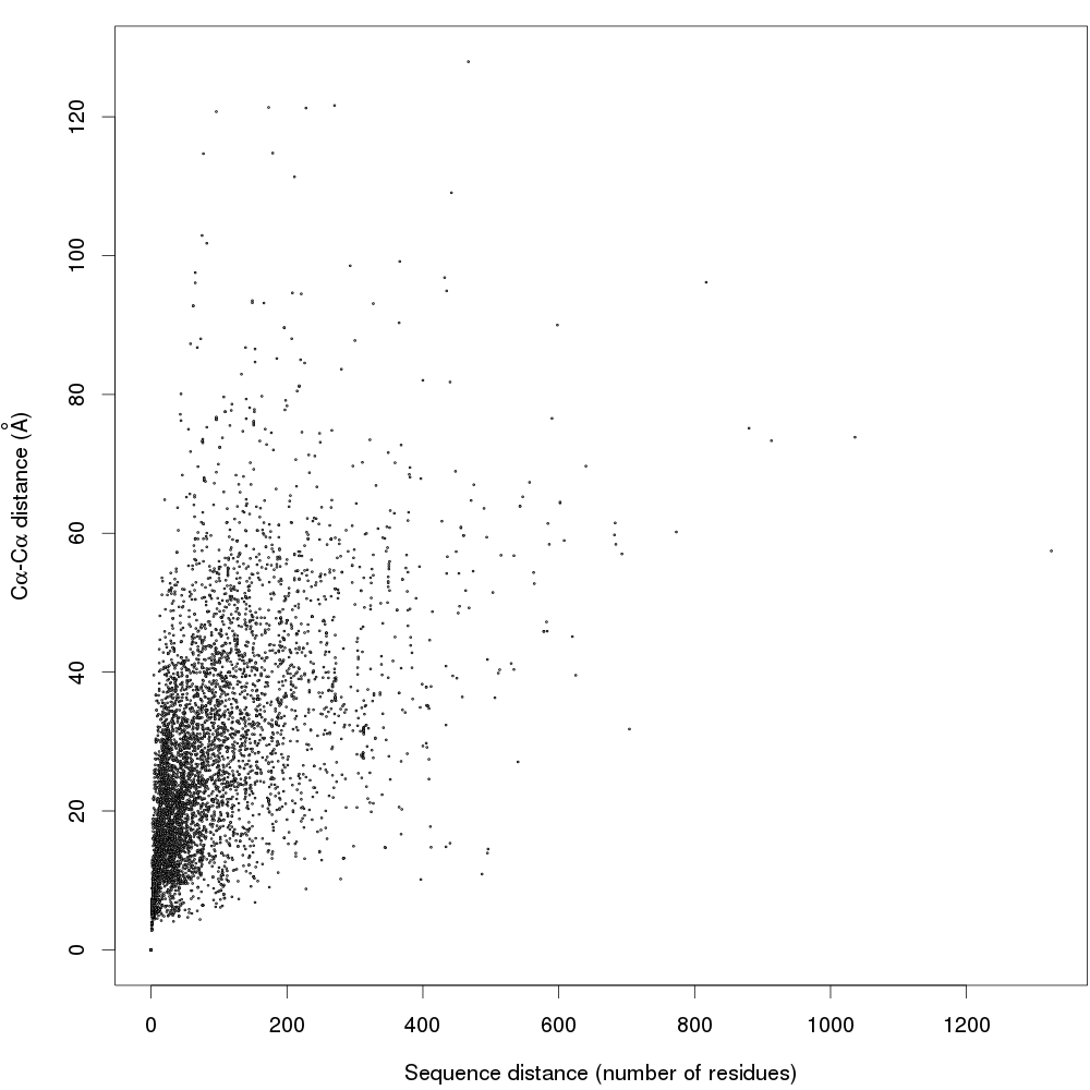
In the article we show that the global B-factor maximum smoothed in a 5-residue window in a PDB chain is often tens of residues away from the maximum in the corresponding BDB chain.
This figure shows correlation of the Cα-Cα distance between the maxima with the distance in primary structure.

References and Further Reading
- Painter, J. and Merritt, E.A. (2005) Acta Crystallogr. D, 61, 465-471.
- Painter, J. and Merritt, E.A. (2006) Acta Crystallogr. D, 62, 439-450.
- Schomaker, V. and Trueblood, K.N. (1968) Acta Crystallogr. B, 24, 63-76.
- Winn, M.D., Isupov, M.N. and Murshudov, G.N. (2001) Acta Crystallogr. D, 57, 122-133.
- Zucker, F., Champ, P. and Merritt, E.A. (2010) Acta Crystallogr. D, 66, 889-900.